Uncovering Hidden Vulnerabilities
Supply chain attacks continue to be a growing problem in security. In the U.S., President Biden’s Executive Order 14208 dedicated a section specifically to providing guidance on software supply chain security. If your solution relies on code provided by another vendor, even if it’s something as fundamental as firmware, it is important to make sure the code is thoroughly tested for vulnerabilities. This is especially important as OT becomes a bigger area of interest for cybercriminals, where vulnerabilities like those recently disclosed by Schneider could allow an attacker to not only gain a foothold in the network, but also cause physical damage.
With vendors leveraging increasingly advanced obfuscation and encryption techniques to protect the confidentiality of their code, finding vulnerabilities can be especially challenging. Another difficulty is the firmware itself becoming a challenge to reverse, if it was compiled for an obsolete architecture and commercial disassemblers can’t properly reconstruct it. The firmware in the Schneider Electric APC PDU is an example of such a code; it has been around for years and is compiled for an old and obsolete version of the Intel 80286 (a chipset from the 80s), which prevents easy reading or inspection.
In this blog, we show how we disassembled the firmware in a Schneider Electric APC PDU, providing insight for others who might run into this problem when analyzing their devices for vulnerabilities.
Extracting Target Files from the Firmware Executable
To start our analysis, we will target the apc_hw05_aos682_rpdu2g680_bootmon109.exe file, which contains a firmware that is compatible with a large set of APC PDUs and UPSs.
If we run this executable file, we can observe that this is more an archive file than an executable. In fact, it extracts eight files, among which three are of interest:
apc_hw05_aos_682.bin
apc_hw05_bootmon_109.bin
apc_hw05_rpdu2g_680.bin
They represent the APC Operating System (AOS), the bootloader and the firmware of the network management card, respectively.
We started our analysis on the AOS binary, but, once loaded into IDA, we run into our first problem: determining which is the target processor. Even by opening the device case, we couldn’t identify the processor model. After some internet forum research, we found that the PDU is used to adopt an Intel 16 bits processor. We tried a different target and found that a generic x86 16 bits protected mode processor showed the best code readability. At this point we were able to find strings and a lot of code, but the disassembler was not able to find any cross references.
After a further exhaustive search on the internet, we were able to find an article from JSOF that addressed our problem. From that article we learned that the processor is a Turbo186: that CPU runs in extended mode, using 24-bits addressing capability, so the target address of a far call can be computed as (segment_base << 8) + offset.
Another important piece of information found in JSOF’s article was the header structure of each module of the APC firmware. Figure 1 shows the header of the apc_hw05_aos_682.bin file. In this picture, several fields are highlighted; in particular, what we are interested in is the “Image base” field, which indicates the starting address of each firmware module.

From Figure 1 we can see that the starting address of the AOS module is 0xC00400. By looking into the other files, we can retrieve the starting address of the rpdu2g (0x900400) and the bootmon (0x0C0000) modules.
At this point it is possible to load the three modules into IDA, specifying the one we got from the file headers as the starting address. For the processor, we need to choose the Intel 80286 protected.
Once the binary is imported into IDA, notice that very few references to strings or code are generated. This is caused by the structure of the Turbo186 assembly code. In fact, it is organized in blocks and the instructions reference to the code addresses with a pattern defined by block_base_address + offset.
To properly rewrite the program, we need to find the table containing the starting address of each code block, but, unfortunately, its representation in the code seems to be scrambled so we cannot read it. Thus, we need to reconstruct it manually.

First, we need to create the strings and convert the firmware bytes to code, whenever it is possible. Then, we leverage the structure of the far calls: Figure 2 shows an example of a far call, where the segment base address is (0x0C004 << 8) and the offset is 0x54C. To find all the segment base addresses we use the “Search for text” command in IDA, and we search the string “call far ptr”. In this way, we get all the far call instructions defined in the code and, with a python parser, we created an ordered list of all the referenced block base addresses. At this point, we wrote an IDA/python script that creates a new IDA segment for each entry of the list. Figure 3 shows a small portion of all the segment we found in the APC firmware.

Putting the Pieces Together: Recreating Code and Data Cross References
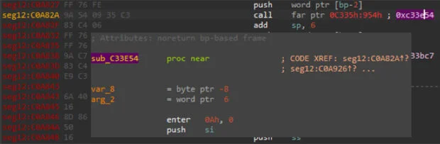
We are now ready to create data and code cross-references; as for the code references, we have already explained how far calls are structured so, once we have set the segments table, we can iterate through the code. For each far call, a new code cross reference (CREF) is created, with the usual target address (segment_base_address << 8) + offset. For better code readability, we can also add a comment near the caller address, specifying the callee address. IDA will automatically reference to it and show a preview of the target code as soon as you hover over the comment with the mouse pointer. Figure 4 shows an example of an address expansion with the corresponding comment.
Once we have recreated all the code references, we can move on to the data references. This time, we will leverage the procedure used by the Turbo186 assembly to pass arguments to subroutines, which present two “push” instructions: the first one pushes the cs register to the stack, while the second pushes the offset of the parameter address with respect to the base address of the segment where these push instructions are defined. If the result of the operation segment_start_address + offset produces the address of a string (as a first step we create the strings), we can create the corresponding DREF. Figures 5a and b show an example.
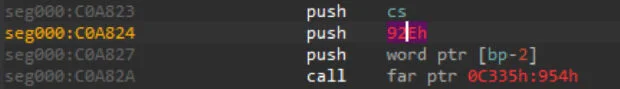

In Figure 5a we notice that at address 0xC0A823 there is a “push cs” and the following instruction is “push 0x92Eh”. We know (from the analysis about code references), that this segment starts at 0xC09B00; if we add the start address of the segment to the immediate value of the push instruction, we obtain 0xC0A42E, which is the address of the string used as argument for the function called at 0xC0A82A (Figure 5b).
The last step of this work consists of creating functions. To do so, we can keep track of all the far calls we previously examined, and, for each of them, consider the first instructions at the target address. If those instructions could represent a function prologue, we can create a function. Furthermore, we need to identify the epilogue of the function in order to properly set the function address range.
Summary
In this post, we outlined the specific methodology used to analyze the firmware of the Schneider Electric APC PDU devices. However, this approach can be used as a framework for how to examine other code compiled for this kind of processor. As we see an ever-increasing number of attacks on OT/IoT devices, understanding how to analyze code compiled on older hardware or obfuscated by the developer becomes increasingly important.